3. Double direct configuration with fluids and temperature
Possible measurements:
- Fault parallel and perpendicular permeability (static and dynamic)
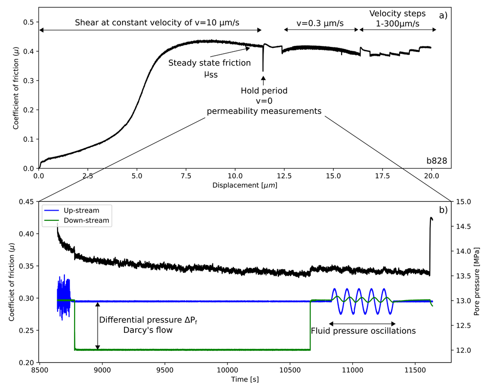
- Fault constitutive frictional properties (velocity steps and slide-hold-slide)
- Unconventional creep experiments with fluid injection
- Ultrasonic P- and S- Wave measurement
- Fault parallel and perpendicular permeability (static and dynamic)
- Fault constitutive frictional properties (velocity steps and slide-hold-slide)
- Unconventional creep experiments with fluid injection
- Ultrasonic P- and S- Wave measurement
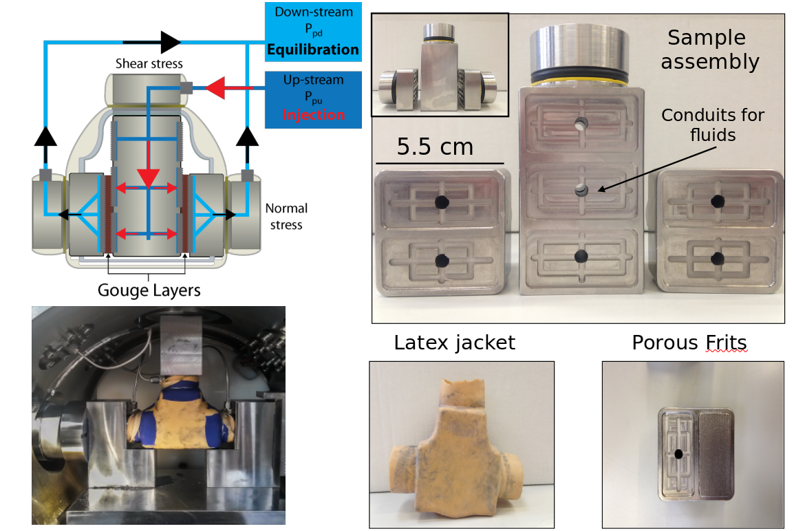
The double direct shear configuration consists of a three forcing bocks assembly, with a central forcing block and two side stationary blocks that sandwich two layers of gouge material. Forcing blocks are equipped with high pressure fittings and internal conduits that provide fluid access to the gouge layers via sintered, stainless steel porous frits with permeability, perm~10-14 m2, which is high when compared with the permeability of the gouge layers (10-17 <perm<10-18 m2) . The frits are press fit into the forcing blocks and used to homogenously distribute fluids to the gouge layer boundaries. Frits were machined with grooves using an EDM technique to avoid damaging the pore structure; grooves are 0.8 mm in height with 1-mm spacing and oriented perpendicular to the shear direction to ensure that shear occurs within the gouge layers and not at the layer boundaries. The nominal frictional contact area is 5.54 cm × 5.55 cm.
Permeability Measurements
During the experiments we can measure permeability during static fault contact or during shear using either the Darcy’s law or the Fluid Pressure Oscillation method. The latter is mostly used to understand permeability evolution during shear slip.
During the experiments we can measure permeability during static fault contact or during shear using either the Darcy’s law or the Fluid Pressure Oscillation method. The latter is mostly used to understand permeability evolution during shear slip.